Signed Distance Fields Part 2: Solid geometry

In the first blog of this series I wrote an introduction to distance fields – a technique for representing geometry in a texture. For each pixel of a distance field texture, we store the distance from that pixel to the edge of the geometry. Using a special shader we can then reconstruct and render that geometry very efficiently. In this episode I’ll expand distance fields to signed distance fields, which are used to represent solid shapes.

The code for this series can be found on git hub here.

From unsigned to signed fields

Previous we saw this distance field for a line segment, and how it could be used to render not just the original line segment, but also fatter/thinner versions of it:

However, what if we want to represent a solid circle with a field. Simple distances are all well and good with a line, but to reconstruct a solid shape, our GPU needs 1 extra piece of information per pixel – is it inside or outside the shape? We achieve this quite simply by using the sign of the distance. A negative value represents a point inside the geometry, and a positive one represents a point outside it:

CircleWithDistances

Here you can see both the stored distances in our field, with those distances also represented as a pixel colour, where green is negative and red is positive. The things to note are:

  • Just as with our earlier distance fields, points on the edge of the circle have distances closest to 0 (though as it happens, in this diagram none of the pixel lies perfectly on the edge of the circle).
  • Points on the inside of the circle have a negative distance, and are shown as green
  • Points on the outside of the circle have a positive distance, and a shown as red

Simple Rendering

The simplest first step to take is to try running our earlier shader against this new texture and see what happens. As a reminder, here’s the code we finished with last time:


fixed4 frag (v2f i) : SV_Target
{
    //sample distance field
    float4 sdf = tex2D(_MainTex, i.uv);

    //combine sdf with offset to get distance
    float d = sdf.r + _Offset;

    //return border or background colour depending on distance from geometry
    if (d < _BorderWidth)
        return _Border;
    else
        return _Background;
}

Running against this new field, surpringly, it ‘just works’:

SolidCircleDrawnWithDistanceFieldShader

With absolutely no changes to code, the old shader correctly renders our circle shape, and the ‘border width’ and ‘offset’ properties both function as they did before. It is easy to see why – our shader simply tests to see if the distance value is less than our border width. As pixels inside the circle store negative distances, these pass that test and end up being rendered as solid.

However, what if we want to take this a step further and introduce separate ‘fill’ and ‘border’ colours for our shape? As it happens, the modifications to our shader are quite simple:

fixed4 frag (v2f i) : SV_Target
{
    //sample distance field
    float4 sdf = tex2D(_MainTex, i.uv);

    //combine sdf with offset to get distance
    float d = sdf.r + _Offset;

    //if distance from border < _BorderWidth, return border.
    //otherwise return _Fill if inside shape (-ve dist) or 
    //_Background if outside shape (+ve dist)
    if (abs(d) < _BorderWidth)
        return _Border;
    else if (d < 0)
        return _Fill;
    else
        return _Background;
}

Here we have made 3 key changes:

  • Added a new shader variable for the fill colour (_Fill)
  • The test that outputs ‘border colour’ now uses the absolute value of the distance, restricting it to pixels that are genuinely on the edge of the geometry
  • If the pixel is not part of the border, but is negative, we output the ‘fill colour;

The result:

SolidCircleWithBorder

For the first time so far, we can also see a clear difference between adjusting _BorderWidth and _Offset. The offset affects the distance value used in all calculations, making the shape as a whole fatter/thinner:

SolidCircleWithOffsets
Circle field rendered with offset parameter of 0 (left), -1.5 (middle) and 1.5 (right)

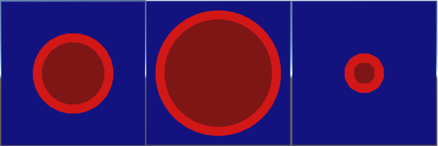
However the border width only affects the border test, making the border fatter or thinner:

SolidCircleWithBorders
Circle field rendered with border width parameter of 0.5 (left), 1.5 (middle) and 0.25 (right)

As you can imagine, with these 2 properties we can now create circles with any radius and border size, all using the original circular distance field from the top of this article.

More complex shapes

Up until now we’ve dealt with some very simple primitives, however signed distance fields are extremely flexible and can be used with any sort of geometry. Whilst I will go into more detail on field generation in a later post, for now, know that we can very easily merge 2 shapes together by sampling the distance for each one and picking the lowest of the 2:

DualCircleField

Here you can see our field for 2 overlapping circles. Note that pixels on the left contain distances to the left circle’s surface, as it is closest, and visa-versa on the right. When applied to this new more complex field, our shader ‘just works’:

DualCircles

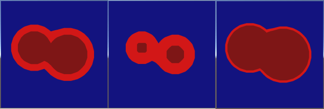
Or some more complex combinations (with an added rectangle!):

WeirdShapes

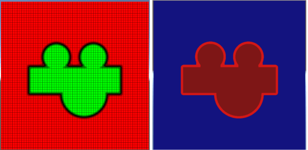
As I mentioned in my previous post, it is still worth remembering that the above images are around 650×650 pixels each, however are generated entirely from a simple 16×16 distance field texture. The most visible artefacts as a result of this low detail are the almost ‘polygonal’ straight lines where we might hope for curves:

LoResArtifacts

However, even stepping up to a relatively low resolution 64×64 texture, these artefacts rapidly become hard to spot:

hires

Well, that’s a good intro to the basics of signed distance fields and how they work. In the next post, I’ll be covering a stumbling block for many – once you’ve accepted the awesomeness of signed distance fields, how do you actually generate them?!

All the code for this series can be found at: https://github.com/chriscummings100/signeddistancefields

Signed Distance Fields Part 3: Bringing it together

Signed Distance Fields Part 1: Unsigned Distance Fields

Welcome to the first blog post on shaderfun.com. It probably won’t be all shaders, and probably not always fun, but I promise lots of interesting code and stuff. Signed distance fields are so awesome that my friends claim I bring them up every time I go to the pub. Whilst this is not true (and neither is the fact that I never buy a pint), they are one of my favourite programming tools these days, so I’ve decided to start this blog off with some signed distance field fun (SDFF).

(Not Signed) Distance Fields

Typically when we create a texture we think of it as a grid of numbers, each of which represents a ‘brightness’. 0 is black, 1 is white. Coloured textures simply extend this concept to store 3 values (or 4 if transparency is included).

Whilst typical textures are very useful for general purpose imagery, they are not particularly good at expressing geometric shapes. This is predominantly down to 2 problems:

  • If the geometry is not perfectly aligned to the pixel grid, it must be approximated, resulting in aliasing effects
  • Low resolution textures scale up very badly, forcing us to store high res textures if we want an accurate representation of our geometry

Distance fields are another way of utilising textures that aim to describe geometry (such as a circle, line or more complex combination of shapes). To achieve this, the value of each pixel represents the distance from the centre of that pixel to the nearest geometry.

In this diagram we can see the distance field for a simple line segment at the centre of a grid:

HorzLineWithDistances
Distances to a line segment at the centre of the image

The same image can be better visualised using a colour to represent the distance of a pixel from our geometry:

HorzLineDistanceField
Distances visualised as shades of red

This technique, originally popularised in games for font rendering has some real benefits. With access to this texture a shader has a lot of extra information about the geometry it contains, and we can use that extra information to achieve a variety of effects.

Bilinear Filtering

Before proceeding, another aspect of shaders and textures needs a mention – texture sampling. Thus far in the above examples we’ve been using a 16×16 texture in point sampling mode. That is, when the GPU wants to get the colour at a given coordinate in the texture, it simply reads the value of the closest pixel, resulting in a blocky effect.

These days most of the time we use textures in bilinear (or trilinear) sampling mode, in which the GPU automatically blends across pixels to get a smoother texture:

SamplingComparison
Comparison of point sampling (left) to bilinear sampling (right) of a simple 64×64 pixel circle drawn in paint

In the case of a distance field, this is equivalent to smoothly sampling the distances stored in our texture:

SDFSamplingComparison
Comparison of point sampling (left) to bilinear sampling (right) when applied to a distance field

Rendering The Geometry

Ok! Armed with a distance field, and a GPU that utilises bilinear filtering to smoothly sample the pixels of that field, lets see what we can build. Our first and simplest shader samples the distance, and outputs a ‘solid’ colour if the pixel is close enough to the edge of the geometry.

To start with, here’s the whole unity shader just to put everything in context:

Shader "Custom/SimpleDistanceField" 
{
    Properties
    {
        _MainTex ("Texture", 2D) = "white" {}
        _BorderWidth("BorderWidth", Float) = 0.5
        _Background("Background", Color) = (0,0,0.25,1)
        _Border("Border", Color) = (0,1,0,1)
    }
    SubShader
    {
        Tags { "RenderType"="Opaque" }
        LOD 100

        Pass
        {
            CGPROGRAM
            #pragma vertex vert
            #pragma fragment frag		
            #include "UnityCG.cginc"

            struct appdata
            {
                float4 vertex : POSITION;
                float2 uv : TEXCOORD0;
            };

            struct v2f
            {
                float2 uv : TEXCOORD0;
                float4 vertex : SV_POSITION;
            };

            //texture info
            sampler2D _MainTex;
            float4 _MainTex_ST;
            float4 _MainTex_TexelSize;

            //field controls
            float _BorderWidth;

            //colours
            float4 _Background;
            float4 _Border;
                        
            //simple vertex shader that fiddles with vertices + uvs of a quad to work nicely in the demo
            v2f vert(appdata v)
            {
                v2f o;
                v.vertex.y *= _MainTex_TexelSize.x * _MainTex_TexelSize.w; //stretch quad to maintain aspect ratio
                o.vertex = UnityObjectToClipPos(v.vertex);
                o.uv = TRANSFORM_TEX(v.uv, _MainTex);
                o.uv = 1 - o.uv; //flip uvs
                return o;
            }

            //distance field fragment shader
            fixed4 frag (v2f i) : SV_Target
            {
                //sample distance field
                float4 sdf = tex2D(_MainTex, i.uv);

                //return border or background colour depending on distance from geometry
                float d = sdf.r;
                if (d < _BorderWidth)
                    return _Border;
                else
                    return _Background;
            }
            ENDCG
        }
    }
}

I won’t go into huge detail, as most of it is boiler plate unity shader code. The interesting bit is inside our ‘frag’ function (the fragment shader):

//distance field fragment shader
fixed4 frag (v2f i) : SV_Target
{
    //sample distance field
    float4 sdf = tex2D(_MainTex, i.uv);

    //return border or background colour depending on distance from geometry
    float d = sdf.r;
    if (d < _BorderWidth)
        return _Border;
    else
        return _Background;
}

Here we sample our texture as normal, but instead of outputting a colour, we interpret the red channel as a distance. If the distance is lower than the supplied _BorderWidth parameter, we output the _Border colour, otherwise we output the _Background colour.

The result of this extremely simple shader is our distance field ‘line’ in all its glory:

HorzLineSDF1Pix

Here we have rendered the line segment geometry with a radius of 0.5 pixels in the texture (known as texels). Visually this yields a solid line 1 texel wide with 2 rounded ends where the bilinear texture sampling has blended the distances stored in neighbouring pixels.

Next, we can add an extra ‘offset’ value to the shader to bias the sampled distance, allowing us to increase or decrease the distance used by our calculations:

//distance field fragment shader
fixed4 frag (v2f i) : SV_Target
{
    //sample distance field
    float4 sdf = tex2D(_MainTex, i.uv);

    //combine sdf with offset to get distance
    float d = sdf.r + _Offset;

    //return border or background colour depending on distance from geometry
    if (d < _BorderWidth)
        return _Border;
    else
        return _Background;
}


The resulting visual effect is that, by adjusting the offset, we can create thinner and fatter lines.

Something really worth remembering here is that the above texture is a mere 16×16 pixels in size, yet the level of detail achieved appears to be much greater. This extremely powerful feature is what makes signed distance fields so great for font rendering – with relatively small amounts of texture space we can efficiently render very highly detailed geometric shapes. The same principle allows us to achieve many other fun useful effects such as outlines, morphing and bloom at a low GPU/memory cost.

Just to finish off this first part, here’s a nice fat line without the nasty grid for you to gaze at:

HorzLineSDF4PixNoGrid

Stay tuned for the next parts of this blog, in which I’m aiming to cover:

  • Full signed distance fields
  • Different techniques (and code!) for generating signed distance fields
  • Some fun effects you can achieve with them

All the code for this series can be found at: https://github.com/chriscummings100/signeddistancefields

Signed Distance Fields Part 2: Solid geometry