Up until now we’ve focused on the concepts of signed distance fields and how to render them using a special shader. However, a place to stumble once you understand these tools is how to get/find/create the fields in the first place. As it happens, there are loads of different ways that vary depending on source data, and performance/quality requirements. At the end of this post you should have a basic (if inefficient) approach to generating fields that works out the box, and is easy to extend.
As always, the full git repo is on github here.
The Field Generator
Having cleaned up the signed distance field renderer in the previous post, we’ll switch to another class called SignedDistanceFieldGenerator. For a full listing, see SignedDistanceFieldGenerator.cs. This class provides 2 facilities:
- Starting/finishing generation by allocating a temporary buffer for
the field, then at the end converting it to a unity texture - A set of utility functions we’ll gradually add to for generating fields in
a variety of ways
Our generator starts with the definition of a field pixel:
public struct Pixel
{
    public float distance;
}
This simple class is used to store the properties of a pixel during generation. It contains just 1 value for now:
distance: as you might expect, this is the calculated signed
distance for the pixel
We have a constructor that does nothing more than allocate a buffer and initialise all the pixels to a very large distance, meaning they will always be interpreted as ‘outside’ the geometry:
public SignedDistanceFieldGenerator(int width, int height)
{
    m_x_dims = width;
    m_y_dims = height;
    m_pixels = new Pixel[m_x_dims * m_y_dims];
    for (int i = 0; i < m_pixels.Length; i++)
        m_pixels[i].distance = 999999f;
}
A couple of accessors to help with reading/writing the field pixels:
Pixel GetPixel(int x, int y)
{
    return m_pixels[y * m_x_dims + x];
}
void SetPixel(int x, int y, Pixel p)
{
    m_pixels[y * m_x_dims + x] = p;
}
And finally, the slightly more complex ‘End’ function, which converts our array of pixels into a texture:
public Texture2D End()
{
    //allocate an 'RGBAFloat' texture of the correct dimensions
    Texture2D tex = new Texture2D(m_x_dims, m_y_dims, TextureFormat.RGBAFloat, false);

    //build our array of colours
    Color[] cols = new Color[m_pixels.Length];
    for (int i = 0; i < m_pixels.Length; i++)
    {
        cols[i].r = m_pixels[i].distance;
        cols[i].g = 0;
        cols[i].b = 0;
        cols[i].a = m_pixels[i].distance < 999999f ? 1 : 0;
    }

    //write into the texture
    tex.SetPixels(cols);
    tex.Apply();
    m_pixels = null;
    m_x_dims = m_y_dims = 0;
    return tex;
}
Within this ‘End’ function, the first step is to allocate a new texture for our field:
Texture2D tex = new Texture2D(m_x_dims, m_y_dims, TextureFormat.RGBAFloat, false);
The texture format used here is 'RGBAFloat'. Unlike most formats, this uses a full floating point value for each colour channel. Whilst expensive (128 bits per pixel!), it is the most convenient format to use for these tutorials, as it allows us to store any numbers in our pixels without worrying about ranges or precision. That said, later in this series we’ll look at techniques for storing fields in much more compact formats.
Next, we generate the colours:
    //build our array of colours
    Color[] cols = new Color[m_pixels.Length];
    for (int i = 0; i < m_pixels.Length; i++)
    {
        cols[i].r = m_pixels[i].distance;
        cols[i].g = 0;
        cols[i].b = 0;
        cols[i].a = m_pixels[i].distance < 999999f ? 1 : 0;
    }
Here, the distance is written into the red channel and if the pixel has a sensible distance (indicating it has been written to), it is assigned an alpha value of 1, so the shader can identify it as containing valid data. Strictly speaking this last bit is unnecessary, but it’ll help with our debugging visualisations later. Eventually we will use the green and blue channels to visualise field gradients, but they’re not necessary right now.
The final step simply writes the colours into the texture, clears out any temporary data and returns:
    //write into the texture
    tex.SetPixels(cols);
    tex.Apply();
    m_pixels = null;
    m_x_dims = m_y_dims = 0;
    return tex;
With this lot written, we can start developing different approaches to fill out that grid of pixels, then convert the result to a texture and render it using our SignedDistanceField class.
Brute Force Geometry
The simplest approach to generation is to write a function for each type of geometric primitive we’re interested in (i.e. line/circle/square) that iterates over / potentially modifies every single pixel in the field (hence brute force).
A line
To begin, lets add the function for a line. We’ll call this one “BFLine” to indicate it uses the brute force approach:
//brute force line generator - iterates over every pixel and calculates signed distance from edge of rectangle
public void BFLine(Vector2 a, Vector2 b)
{
    Vector2 line_dir = (b - a).normalized;
    float line_len = (b - a).magnitude;

    for (int y = 0; y < m_y_dims; y++)
    {
        for (int x = 0; x < m_x_dims; x++)
        {
            //mathematical function to get distance from a line
            Vector2 pixel_centre = new Vector2(x + 0.5f, y + 0.5f);
            Vector2 offset = pixel_centre - a;
            float t = Mathf.Clamp(Vector3.Dot(offset, line_dir), 0f, line_len);
            Vector2 online = a + t * line_dir;
            float dist_from_edge = (pixel_centre - online).magnitude;

            //update the field with the new distance
            Pixel p = GetPixel(x, y);
            if (dist_from_edge < p.distance)
            {
                p.distance = dist_from_edge;
                SetPixel(x, y, p);
            }
        }
    }
}
This function:
- Iterates over every pixel in the field, and for each one calculates the distance from the centre of the pixel to the line
- If the calculated distance is lower than the existing one, update it.
The idea here follows naturally from our definition of a signed distance field – each pixel contains the distance to the closest edge of the geometry. A line is really just a single edge when you think about it, so we check every pixel in the field, and if the distance to the line is lower than the distance we have stored, we update it.
I’m going to try and avoid covering the maths for every shape in this blog, as the info is out there and I don’t want to end up writing a maths blog just yet! As this is our first shape though, here it is broken down a little more:
//calculate the centre of the pixel (the +0.5 is because we want the centre, not the corner)
Vector2 pixel_centre = new Vector2(x + 0.5f, y + 0.5f);

//calculate the offset from start of the line (a) to the centre of the pixel
Vector2 offset = pixel_centre - a;

//use a dot product to project the offset onto the line, giving us a 't' value
//then clamp the 't' value to between 0 and line len
float t = Mathf.Clamp(Vector3.Dot(offset, line_dir), 0f, line_len);

//calculate the position of the point of the line using our calculated/clamped t
Vector2 online = a + t * line_dir;

//finally, work out the distance from our pixel to the point on the line
float dist_from_edge = (pixel_centre - online).magnitude;
Before proceeding, lets go back to SignedDistanceField.cs. Right at the bottom you’ll find a ‘custom inspector’ (see the Unity docs here for more info), which lets us add a few extra tools to the inspector for our field object. Within the OnInspectorGUI function is the following code:
SignedDistanceField field = (SignedDistanceField)target;
if (GUILayout.Button("Generate Centre Line"))
{
    SignedDistanceFieldGenerator generator = new SignedDistanceFieldGenerator(16,16);
    generator.BFLine(new Vector2(3.5f, 8.5f), new Vector2(12.5f, 8.5f));
    field.m_texture = generator.End();
}
This button contains the simple code to:
- Create temporary signed distance field generator for a 16×16 field
- Add a line to it using
BFLine - Generate the texture by calling ‘end’ and point our field at it
The resulting render is the one we generated right at the start of this blog:

A circle
Let’s now add the same function for a circle:
//brute force circle generator - iterates over every pixel and calculates signed distance from edge of circle
public void BFCircle(Vector2 centre, float rad)
{
    for (int y = 0; y < m_y_dims; y++)
    {
        for (int x = 0; x < m_x_dims; x++)
        {
            Vector2 pixel_centre = new Vector2(x + 0.5f, y + 0.5f);
            float dist_from_edge = (pixel_centre - centre).magnitude - rad;

            Pixel p = GetPixel(x, y);
            if (dist_from_edge < p.distance)
            {
                p.distance = dist_from_edge;
                SetPixel(x, y, p);
            }
        }
    }
}
Once again, we’re iterating over every pixel, calculating the distance to the edge of the circle, and updating the stored distance if necessary. A new feature in this case however is that the circle is solid, so we generate negative values for pixels inside the circle, and positive values for pixels outside the circle.
As before, we can also add a button to the custom inspector to generate a field using this new function. There’s a few in there, but this is the first one that’s a little more fun:
if (GUILayout.Button("Generate 2 circles"))
{
    SignedDistanceFieldGenerator generator = new SignedDistanceFieldGenerator(16, 16);
    generator.BFCircle(new Vector2(5, 7), 3);
    generator.BFCircle(new Vector2(10, 8), 3.5f);
    field.m_texture = generator.End();
}
Remember our generator doesn’t just write into the pixel buffer – it first checks if the new distance is a better candidate than the stored one. As a result, we can use the function to add a combination of 2 circles, simply by calling it twice with different parameters.
If I remember correctly, the result should be something along these lines:
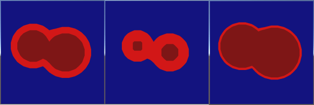
Note: I may have fiddled with positions/sizes since I took that snap shot. The principle is the same but the numbers might not be!
A rectangle
Without going into too much more detail, here’s the code to generate a rectangle
//brute force rectangle generator - iterates over every pixel and calculates signed distance from edge of rectangle
public void BFRect(Vector2 min, Vector2 max)
{
    Vector2 centre = (min + max) * 0.5f;
    Vector2 halfsz = (max - min) * 0.5f;

    for (int y = 0; y < m_y_dims; y++)
    {
        for (int x = 0; x < m_x_dims; x++)
        {
            //get centre of pixel
            Vector2 pixel_centre = new Vector2(x + 0.5f, y + 0.5f);

            //get offset, and absolute value of the offset, from centre of rectangle
            Vector2 offset = pixel_centre - centre;
            Vector2 absoffset = new Vector2(Mathf.Abs(offset.x), Mathf.Abs(offset.y));

            //calculate closest point on surface of rectangle to pixel
            Vector2 closest = Vector2.zero;
            bool inside;
            if (absoffset.x < halfsz.x && absoffset.y < halfsz.y)
            {
                //inside, so calculate distance to each edge, and choose the smallest one
                inside = true;
                Vector2 disttoedge = halfsz - absoffset;
                if (disttoedge.x < disttoedge.y)
                    closest = new Vector2(offset.x < 0 ? -halfsz.x : halfsz.x, offset.y);
                else
                    closest = new Vector2(offset.x, offset.y < 0 ? -halfsz.y : halfsz.y);
            }
            else
            {
                //outside, so just clamp to within the rectangle
                inside = false;
                closest = new Vector2(Mathf.Clamp(offset.x, -halfsz.x, halfsz.x), Mathf.Clamp(offset.y, -halfsz.y, halfsz.y));
            }
            closest += centre;

            //get offset of pixel from the closest edge point, and use to calculate a signed distance
            Vector3 offset_from_edge = (closest - pixel_centre);
            float dist_from_edge = offset_from_edge.magnitude * (inside ? -1 : 1);

            Pixel p = GetPixel(x, y);
            if (dist_from_edge < p.distance)
            {
                p.distance = dist_from_edge;
                SetPixel(x, y, p);
            }
        }
    }
}
That one may look a little scarier, but only because working out the signed distance to the edge of a rectangle is slightly more complex. If inside, we find the closest point by picking the closest edge and calculating the distance to it, then negate the result (as it’s inside). If outside, we simply clamp our pixel’s centre to within the rectangle, and calculate the distance from the unclamped position to the clamped one.
By now you’re hopefully seeing a pattern appearing, and by the end of this blog there may well be a few more ‘brute force’ functions to play with checked into the git repo.
Indeed, as relatively simple algorithms exist to calculate the distance from any pixel to any edge of any polygon (convex or concave), and also to calculate whether that pixel is inside or outside the polygon, we can generate a field for any arbitrary closed polygon. If the reader wants to have a go at this, here’s a couple of clues:
- You already have the code to find the closest distance from a point to a line (aka edge!)
- You know combining multiple shapes simply involves comparing the existing pixel distance to your new candidate distance.
- To find out if a point is inside or outside a polygon, you simply need to draw a line from anywhere outside your shape to your point, and see how
many edges it hits along the way. Check out the algorithm
here
Some problems!
An astute (aka picky!) reader might have noticed a few issues or apparent inconsistencies with the algorithms I’ve described so far. The first point of possible confusion is the slightly misleading ‘is pixel closer’ test:
Pixel p = GetPixel(x, y);
if (dist_from_edge < p.distance)
This is used extensively throughout the code, but at first glance it appears there may be a problem. The distance test works for positive numbers, but for negative numbers, it will technically pass if the distance to the edge of our new shape is closer than the stored one (e.g. -10 is less than -1)!
Fortunately this is not a bug. Currently we are dealing with what are known as Union operations in Constructive Solid Geometry. In simple terms, we want to combine the solid bits of the existing shape with the shape we’re adding. As such, for pixels outside the geometry, we want to keep the closest pixels, but for pixels inside the geometry, we want to keep the deepest pixels.
A scarier problem that’s a little harder to see is that our field can actually become genuinely inconsistent! Lets generate 2 very close rectangles in a relatively hi res (64×64) field:
SignedDistanceFieldGenerator generator = new SignedDistanceFieldGenerator(64, 64);
generator.BFRect(new Vector2(4, 4), new Vector2(60, 35));
generator.BFRect(new Vector2(4, 34), new Vector2(60, 60));
field.m_texture = generator.End();
The result:

At first glance, all looks fine, but what if we go back to visualising the field:

By fiddling with the distance visualiser a bit (see the distance visualisation scale property in the shader), we can clearly show the makeup of our field, the centre line is clearly wrong. Indeed, there shouldn’t actually a centre line!
At its worst, the centre of the rectangle should contain the biggest (negative) distance (it is, after all, the ‘deepest’ pixel), however the distance stored is almost 0. The reason is clear when looking back at our generator. The centre pixel was very close to an inside edge of both rectangles, ergo we’ve only ever tried to write a distance close to 0 into it. In general terms, our distances are correct for outside the solid geometry, but have become inconsistent inside the solid geometry.
This inconsistency rears it ugly head in practice when we try to add a border:

Our border shader algorithm from earlier in the blog assigns a different colour to pixels close to the edge, both inside and outside. As a result, we’ve incorrectly rendered an edge inside the shape.
There’s 2 real approaches to dealing with this. First up, we could just ignore the problem and work around it! Sounds a bit crazy, but sometimes it’s better to ask how you can achieve your goal with the tools you have, rather than spend lots of time making the tools perfect. We could for example create a perfectly reasonable border effect by only colouring pixels outside the field, making the dodgy internal pixels irrelevant. Indeed, many applications deal perfectly well with field inconsistencies, so spending valuable CPU fixing things may be a waste of time! However, if like the Borg perfection be your goal, the next post on sweeping should make you feel much better.
Lastly is our old friend – performance. Our current approach involves iterating over every pixel for every piece of geometry. With the simple stuff so far that’s all well and good, but what if we wanted to render a complex polygon with 5000 edges into a 512*512 texture? 1310720000 operations is what! Fortunately, as we shall see, sweeping comes to the rescue here too.
A quick word on fonts
Right at the start of this series I mentioned SDFs in games had been popularised by fonts, and this post may have taken you some way to seeing why. True type fonts effectively contain a lot of vector based geometry, ideally suited for generating signed distance fields even with the simple approach described above.
Unfortunately, loading ttf files and interpreting their geometry is probably a series in itself. If the reader is interested however, a quick google will reveal a good few c# libraries for loading font geometry. Alternatively, the excellent (and now free) Text Mesh Pro for Unity is SDF driven, and I believe makes it possible to access the raw field data it generates.
Summary
By the time this series is complete, the generator checked in will probably have more functionality than that covered so far. However, with just the tools in this post you now have the power to generate functional signed distance fields. The same principles can even be applied in 3D to voxels, which I may cover down the line! Next up, we’ll move on to refinement/optimisation of fields with an approach called sweeping and look at ways to use it for generating fields from images.
Signed Distance Fields Part 5: Faster generation and sweeping

Great explanations, and obviously you were very into this 🙂
Do you have any suggestions for how to do unions of signed distance fields in a shader? My thought was to try out rendering the signed distance fields from several objects into a render texture (and then draw the actual union object using that render texture with another shader).
LikeLike
Hi Baris. Absolutely – this is a common thing. In the simplest case, all you need to do is provide your shader with both fields and take the ‘min’ (I think – though check the blog) of each, just as with unions as normal. As in the blog, this does start to fall apart if you want to utilize sampling the field outside of the border. ShaderFun has quite a few good examples of this
LikeLike
Hey, thanks for the quick reply! If I’m understanding correctly, in this suggestion, each field would need to be passed to the shader as a texture so the shader combines everything? I was thinking this may not be ideal for several (or more) objects, so I was trying to find a way to render objects one by one into a combined distance field and “blend” with the results already there.
I’m fine with the math of the union operation itself, I think.
LikeLike
Ah, then yes – applying them sequentially in a compute shader would probably be the right way to go. That way you can write a compute shader that samples another field texture, or even one that just generates a certain shape.
LikeLike