Signed Distance Fields Part 5: Faster generation and sweeping

In the previous post we looked at the basics of signed distance field generation. Having setup a framework for generating a field, we wrote a series of functions for adding different shapes, all of which:

  • Iterated over every pixel in the field
  • Calculated the distance to the shape at the centre of the pixel
  • Updated the pixel in the field by comparing the new distance to the current one

And of course, here is the git hub repo with it all in!

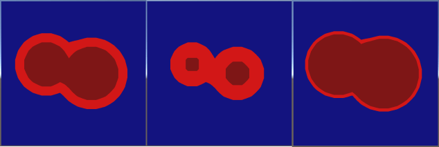
The process worked well, but also highlighted some inconsistencies when combining shapes, demonstrated when drawing 2 rectangles very close together:

BigOverlapping3
Artifacts overlapping 2 rectangles. Left: the combined rectangles with a small border. Middle: the resulting distance field showing an error. Right: the resulting artifacts when using a big border.

The algorithm has no way of knowing that the central pixels of the large rectangle become very ‘deep’ when the 2 smaller rectangles are drawn overlapping one another. This inconsistency breaks the border effect as shown in the right hand image.

In addition to errors, the algorithm has to iterate over every pixel for every shape drawn, so can get slow pretty quickly!

Bounded/padded shapes

To begin, we’ll attempt to speed things up by implementing a simple optimisation. Rather than updating the entire field for every shape, we’ll pick a subset of pixels to update, and leave the rest alone. This will be substantially faster, as a shape that only affects a small area of the field will only have to iterate over a small number of pixels.

To start, lets create a couple of helpers:


//simple function to clamp an integer xy coordinate to a valid pixel
//coordinate within our field
void ClampCoord(ref int x, ref int y)
{
    if (x = m_x_dims) x = m_x_dims - 1;
    if (y = m_y_dims) y = m_y_dims - 1;
}

This very basic function (which we’ll use later) just clamps a coordinate to within the dimensions of our field.

Building on that, a slightly more complex one:


//takes an axis aligned bounding box min/max, along with a padding value, and 
//outputs the integer pixel ranges to iterate over when using it fill out a field
void CalcPaddedRange(Vector2 aabbmin, Vector2 aabbmax, float padding, 
                     out int xmin, out int ymin, out int xmax, out int ymax)
{
    //subtract the padding, and floor the min extents to an integer value
    xmin = Mathf.FloorToInt(aabbmin.x-padding);
    ymin = Mathf.FloorToInt(aabbmin.y-padding);

    //add the padding and ceil the max extents to an integer value
    xmax = Mathf.CeilToInt(aabbmax.x+padding);
    ymax = Mathf.CeilToInt(aabbmax.y+padding);

    //clamp both coordinates to within valid range
    ClampCoord(ref xmin, ref xmax);
    ClampCoord(ref ymin, ref ymax);
}

This function takes an axis aligned bounding box – aka a none rotated rectangle. It is described by the position of its top left corner (aabbmin), and the position of its bottom right corner (aabbmax). In addition, the function takes a padding value, which we’ll use to fatten the box. It then proceeds to calculate the integer range of pixels we’d need to loop over in order to touch every single pixel within the fattened box.

Now to get moving. Lets add new function in SignedDistanceFieldGenerator.cs to draw a line, which, for want of a better naming convention we’ll call PLine as it is a padded line.


//generates a line, writing only to the pixels within a certain distance
//of the line
public void PLine(Vector2 a, Vector2 b, float pad)
{
    //calculate axis aligned bounding box of line, then use to get integer
    //range of pixels to fill in
    Vector2 aabbmin = Vector2.Min(a, b);
    Vector2 aabbmax = Vector2.Max(a, b);
    int xmin, ymin, xmax, ymax;
    CalcPaddedRange(aabbmin, aabbmax, pad, 
                    out xmin, out ymin, out xmax, out ymax);

    Vector2 line_dir = (b - a).normalized;
    float line_len = (b - a).magnitude;

    for (int y = ymin; y <= ymax; y++)
    {
        for (int x = xmin; x <= xmax; x++)
        {
            //mathematical function to get distance from a line
            Vector2 pixel_centre = new Vector2(x + 0.5f, y + 0.5f);
            Vector2 offset = pixel_centre - a;
            float t = Mathf.Clamp(Vector3.Dot(offset, line_dir), 0f, line_len);
            Vector2 online = a + t * line_dir;
            float dist_from_edge = (pixel_centre - online).magnitude;

            //update the field with the new distance
            Pixel p = GetPixel(x, y);
            if (dist_from_edge < p.distance)
            {
                p.distance = dist_from_edge;
                SetPixel(x, y, p);
            }
        }
    }
}

This is only a slight modification of the earlier brute force implementation. At the beginning of the function the axis aligned bounding box of the line is calculated using its start/end points (a and b):


    Vector2 aabbmin = Vector2.Min(a, b);
    Vector2 aabbmax = Vector2.Max(a, b);

This is then passed into our CalcPaddedRange function, along with a new pad parameter, which outputs the integer range of pixels covered by the fattened bounding box:


    int xmin, ymin, xmax, ymax;
    CalcPaddedRange(aabbmin, aabbmax, pad, 
                    out xmin, out ymin, out xmax, out ymax);

The final change is the loops. Where previously they iterated over every pixel (starting from 0, going up to the width/height of the field), they now only iterate over the calculated range of pixels:


for (int y = ymin; y <= ymax; y++)
{
    for (int x = xmin; x <= xmax; x++)
    {

That’s the lot for this first section – everything else is identical to our earlier brute force version. We’ve not changed the algorithm for drawing a line in the slightest. All we’ve done is work out a reduced number of pixels to fill in.

As with our earlier tests, we can now add a button in SignedDistanceField.cs to generate a padded line:


        if (GUILayout.Button("Padded line"))
        {
            SignedDistanceFieldGenerator generator = new SignedDistanceFieldGenerator(32, 32);
            generator.PLine(new Vector2(8, 15), new Vector2(23, 20), 5);
            field.m_texture = generator.End();
        }

This is a roughly diagonal line in a 32×32 field, with a padding of 5 pixels. At first glance, the resulting render (with a border width of 1 pixel) looks perfectly good:

PaddedLine
Diagonal line with 1 pixel border

However, lets look at the distance visualisation:

PaddedLineDist
Distance visualisation with low scale to show unwritten outer pixels

Our distance visualiser renders a shade of red for positive distances to the nearest pixel, but by scaling the shade down, we can see that outside of the bounding box there’s lots of pixels with a huge distance value where we haven’t yet written anything.

The issue with this approach rears it’s ugly head when we try to make the line get fatter. Lets instead go back to rendering it as normal, but with a border width of about 6 pixels:

PaddedLineChopped
Chopping artefacts due to a lack of valid pixels

Our line has now been chopped off at the edges where we hit pixels that think they’re miles away from the edge of anything!

The reader might point out at this stage that rather than make things better, I’ve actually made things worse. On top of the earlier issues with field inconsistencies, we now have to deal with only partial field data. However, even without further refinement this technique is frequently put to work, as many uses of signed distance fields don’t care about every pixel – often the important ones are very close to the edge or inside of the geometry.

Assume, for example, I knew in my game I was never going to try and create borders fatter than 4 pixels. In that situation, generating all my field shapes with a padding of 5 pixels will give me all the data I need, and may save a lot of time.

Whilst I won’t touch upon it yet, many uses of signed distance fields avoid trying to even store data for empty pixels. When 3D voxels come into play, memory runs out very quickly – a 1024x1024x1024 voxel grid of 4 byte floating point distances would take 4GB of memory! Instead, techniques such as sparse octtrees are used, which can store hi resolution voxel data close to the surface of the geometry, but little to no data for voxels far from the surface.

Before proceeding, PCircle and PRect have also been added. As with the PLine function, these are both almost identical to their brute force counterparts, with the added use of the bounding box.

For a circle, the bounding box is calculated by simply building a square centred at the centre of the circle, with a width and height of 2 * the radius:


//circle bounding box calculation - a square that surrounds the circle
Vector2 aabbmin = centre - Vector2.one * rad;
Vector2 aabbmax = centre + Vector2.one * rad;
int xmin, ymin, xmax, ymax;
CalcPaddedRange(aabbmin, aabbmax, pad, 
                out xmin, out ymin, out xmax, out ymax);


And for a rectangle (aka a box) the bounding box is, you guessed it, the box!


//rectangle bound box 'calculation' - just use the min/max of the rectangle
Vector2 aabbmin = min;
Vector2 aabbmax = max;
int xmin, ymin, xmax, ymax;
CalcPaddedRange(aabbmin, aabbmax, pad, 
                out xmin, out ymin, out xmax, out ymax);

Sweeping

If you really want a clean signed distance field, you’re going to have to sweep it (hahaha yeah I went there). With this technique we assume that the only accurate pixels in the field are those that lie on the edge of the geometry, and that any others may have suffered inconsistencies, or not even been written to at all.

The most common sweeping algorithm has such a great name it has always to be written in full… yes, it’s the 8-points Signed Sequential Euclidean Distance Transform. Catchy! I haven’t actually managed to track down the original paper on it, however Richard Mitton on Coders Notes presents a nice and clean implementation in c++. The one we’ll use for this blog is largely a C# port of his work.

First up, a quick function to identify if a pixel is ‘outside’ or ‘inside’ the surface:


bool IsOuterPixel(int pix_x, int pix_y)
{
    if (pix_x < 0 || pix_y = m_x_dims || pix_y >= m_y_dims)
        return true;
    else
        return GetPixel(pix_x, pix_y).distance >= 0;
}

This really just returns true if the distance value is greater than 0, with an extra catch to treat pixels outside the bounds of the field as outside the geometry.

The algorithm starts by iterating over the existing pixels and clearing out anything that doesn’t contain reliable data. The metric we’ll use is whether a pixel is an edge pixel, defined by this little helper:


bool IsEdgePixel(int pix_x, int pix_y)
{
    bool is_outer = IsOuterPixel(pix_x, pix_y);
    if (is_outer != IsOuterPixel(pix_x - 1, pix_y - 1)) return true; //[-1,-1]
    if (is_outer != IsOuterPixel(pix_x, pix_y - 1)) return true;     //[ 0,-1]
    if (is_outer != IsOuterPixel(pix_x + 1, pix_y - 1)) return true; //[+1,-1]
    if (is_outer != IsOuterPixel(pix_x - 1, pix_y)) return true;     //[-1, 0]
    if (is_outer != IsOuterPixel(pix_x + 1, pix_y)) return true;     //[+1, 0]
    if (is_outer != IsOuterPixel(pix_x - 1, pix_y + 1)) return true; //[-1,+1]
    if (is_outer != IsOuterPixel(pix_x, pix_y + 1)) return true;     //[ 0,+1]
    if (is_outer != IsOuterPixel(pix_x + 1, pix_y + 1)) return true; //[+1,+1]
    return false;
}

Here the pixel is first identified as an outer or inner one. It is then compared to all 8 of its neighbours. If an outer pixel has any inner neighbours, its on an edge, and visa-versa.

With these 2 tools, the ‘clear’ function is as follows:


public void ClearNoneEdgePixels()
{
    for (int y = 0; y < m_y_dims; y++)
    {
        for (int x = 0; x  0 ? 99999f : -99999f;
            SetPixel(x,y,pix);
        }
    }
}

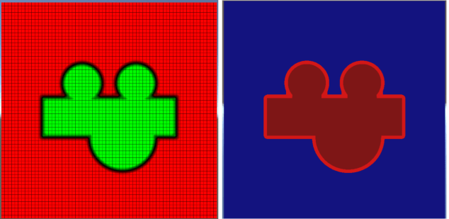
This iterates over every pixel, and identifies any that are not on an edge. In these cases we basically want to update the pixel to say “we still know if you’re inside or outside, but we have no idea how far you are from the surface”. To achieve this the pixel is assigned either a negative or positive very big number. Here’s a couple of examples of the distance visualiser before and after a clear:

ClearNoneEdge

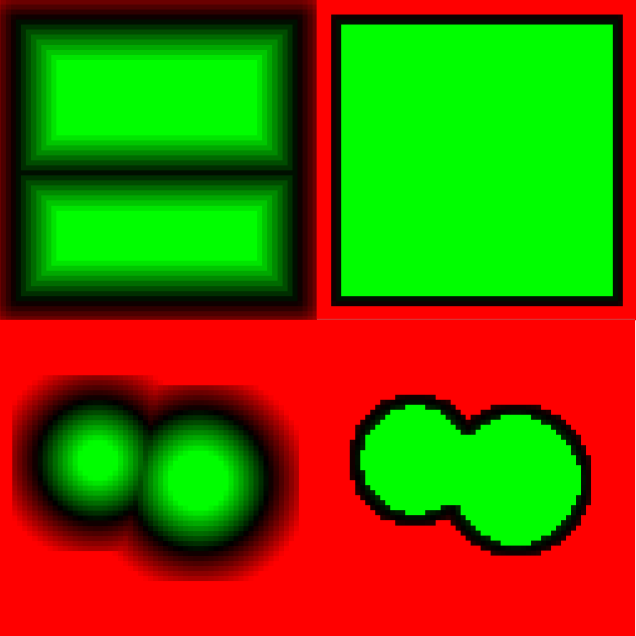
In both examples, on the left is a field generated using one of the earlier functions, while the right shows what happens when the ClearNoneEdgePixels function is applied. Be aware for the remainder of the post I’ve switched to point sampled rendering to clearly show individual pixels, hence the ‘blocky’ look!

The reader might note here that most of the soft edges of the ‘padded circles’ have been obliterated, indicating they could have been generated with very tight padding with no negative consequences.

The sweeping algorithm is much simpler if it doesn’t have to worry about outsides/insides or positive/negative distances. As a result, the common approach is to run the algorithm once for inner pixels, and once for outer pixels, then combine the result at the end. To achieve this, we build 2 separate grids:


//reads current field into 2 grids - 1 for inner pixels and 1 for outer pixels
void BuildSweepGrids(out float[] outside_grid, out float[] inside_grid)
{
    outside_grid = new float[m_pixels.Length];
    inside_grid = new float[m_pixels.Length];
    for (int i = 0; i < m_pixels.Length; i++)
    {
        if (m_pixels[i].distance < 0)
        {
            //inside pixel. outer distance is set to 0, inner distance
            //is preserved (albeit negated to make it positive)
            outside_grid[i] = 0f;
            inside_grid[i] = -m_pixels[i].distance;
        }
        else
        {
            //outside pixel. inner distance is set to 0,
            //outer distance is preserved
            inside_grid[i] = 0f;
            outside_grid[i] = m_pixels[i].distance;
        }
    }
}

When hitting a +ve pixel, the distance is written to the outer grid, but 0 is written to the inner grid, causing the inner sweep to ignore it.

Similarly, when hitting a -ve pixel, the distance is written (negated) to the inner grid, but 0 is written to the outer grid, causing the outer sweep to ignore it.

The core of this, and indeed many sweep algorithms can be seen in the following diagram:

SweepDist

In knowing the distance from B to its nearest edge point, we can take a guess at the distance from A to that same edge point, by taking the distance from A to B, and adding it to the distance from B to the edge.

It’s worth noting that the result isn’t perfect – the calculation gives us an upper bound for the distance from A to the edge. In reality, the distance from A to the edge is a little shorter, as shown here:

SweepDist2

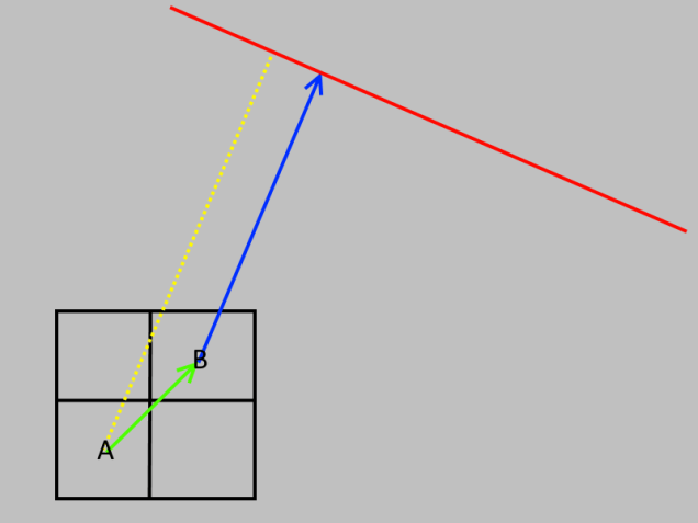
With some cleverer algorithms it is possible to refine these errors a little, but, for many use cases they can be ignored with minimal issues.

Armed with this observation, we can introduce the Compare function:


//compares a pixel for the sweep, and updates it with a new distance if necessary
public void Compare(float[] grid, int x, int y, int xoffset, int yoffset)
{
    //calculate the location of the other pixel, and bail if in valid
    int otherx = x + xoffset;
    int othery = y + yoffset;
    if (otherx < 0 || othery = m_x_dims || othery >= m_y_dims)
        return;

    //read the distance values stored in both this and the other pixel
    float curr_dist = grid[y * m_x_dims + x];
    float other_dist = grid[othery * m_x_dims + otherx];

    //calculate a potential new distance, using the one stored in the other pixel,
    //PLUS the distance to the other pixel
    float new_dist = other_dist + Mathf.Sqrt(xoffset * xoffset + yoffset * yoffset);

    //if the potential new distance is better than our current one, update!
    if (new_dist < curr_dist)
        grid[y * m_x_dims + x] = new_dist;
}

This function takes a pixel (A) at coordinate [x,y], and another pixel (B) at coordinate [x+xoffset,y+yoffset]. Both pixels may already have valid distances associated with them, or they may still contain really-big-number. A new candidate distance is calculated by adding the distance, A->B, to the distance, B->edge. If the new distance is better than the current one, it is updated.

Now for the backbone of the sweep – the SweepGrid function:


public void SweepGrid(float[] grid)
{
    // Pass 0
    //loop over rows from top to bottom
    for (int y = 0; y < m_y_dims; y++)
    {
        //loop over pixels from left to right
        for (int x = 0; x = 0; x--)
        {
            Compare(grid, x, y, 1, 0);
        }
    }

    // Pass 1
    //loop over rows from bottom to top
    for (int y = m_y_dims - 1; y >= 0; y--)
    {
        //loop over pixels from right to left
        for (int x = m_x_dims - 1; x >= 0; x--)
        {
            Compare(grid, x, y, 1, 0);
            Compare(grid, x, y, 0, 1);
            Compare(grid, x, y, -1, 1);
            Compare(grid, x, y, 1, 1);
        }

        //loop over pixels from left to right
        for (int x = 0; x < m_x_dims; x++)
        {
            Compare(grid, x, y, -1, 0);
        }
    }
}

Utilising the Compare function, this sweeps over all the pixel rows, first from top to bottom, then from bottom to top. For each row, it sweeps from left to right, and right to left. Within these loops, pixels are compared to their neighbours, and distances updated if better ones are found. I don’t want to go into the exact proof that the above set of loops guarantee the correct result, as that’s a scientific paper in itself! However, these videos hopefully show the process in action very convincingly:

The final function that glues it all together and writes the grids back into the field pixels is Sweep:


public void Sweep()
{
    //clean the field so any none edge pixels simply contain 99999 for outer
    //pixels, or -99999 for inner pixels
    ClearNoneEdgePixels();

    //seperate the field into 2 grids - 1 for inner pixels and 1 for outer pixels
    float[] outside_grid,inside_grid;
    BuildSweepGrids(out outside_grid, out inside_grid);

    //run the 8PSSEDT sweep on each grid
    SweepGrid(outside_grid);
    SweepGrid(inside_grid);

    //write results back
    for (int i = 0; i < m_pixels.Length; i++)
        m_pixels[i].distance = outside_grid[i] - inside_grid[i];
}

The only new functionality here is the last write-back, which subtracts the inner grid from the outer one. This in effect just combines the 2 grids, and makes the inner pixels negative again.

If you’re interested, I made the videos using a slightly body new class called AnimatedSweep. It’s not meant to be a shining example of nice code, but it’s there if you want a peak!

Summary

Phew! Turns out sweeping takes more to explain than planned. By now you’ve got a good understanding of writing to distance fields, a way of minimizing performance cost of doing so and a robust technique for cleaning up errors.

We’ve definitely not covered everything on sweeping here. The 8SSD method described so far is technically an optimal version of an ‘8 tap’ algorithm, meaning for any given pixel, all 8 neighbours are checked and the best candidate is selected. In addition, we have the less accurate ‘4 tap’ algorithms which ignore the diagonals, and the more mathematical but highly accurate eikonal equation that I may go over later in the series.

Next episode will add a final powerful tool to your 2D SDF generation kit – generating from images created in anything from MS Paint to Adobe Photoshop.

Check out the code here for the latest stuff.

Signed Distance Fields Part 6: Images

Signed Distance Fields Part 4: Starting Generation

Up until now we’ve focused on the concepts of signed distance fields and how to render them using a special shader. However, a place to stumble once you understand these tools is how to get/find/create the fields in the first place. As it happens, there are loads of different ways that vary depending on source data, and performance/quality requirements. At the end of this post you should have a basic (if inefficient) approach to generating fields that works out the box, and is easy to extend.

As always, the full git repo is on github here.

The Field Generator

Having cleaned up the  signed distance field renderer in the previous post, we’ll switch to another class called SignedDistanceFieldGenerator. For a full listing, see SignedDistanceFieldGenerator.cs. This class provides 2 facilities:

  • Starting/finishing generation by allocating a temporary buffer for
    the field, then at the end converting it to a unity texture
  • A set of utility functions we’ll gradually add to for generating fields in
    a variety of ways

Our generator starts with the definition of a field pixel:


public struct Pixel
{
    public float distance;
}

This simple class is used to store the properties of a pixel during generation. It contains just 1 value for now:

  • distance: as you might expect, this is the calculated signed
    distance for the pixel

We have a constructor that does nothing more than allocate a buffer and initialise all the pixels to a very large distance, meaning they will always be interpreted as ‘outside’ the geometry:


public SignedDistanceFieldGenerator(int width, int height)
{
    m_x_dims = width;
    m_y_dims = height;
    m_pixels = new Pixel[m_x_dims * m_y_dims];
    for (int i = 0; i < m_pixels.Length; i++)
        m_pixels[i].distance = 999999f;
}

A couple of accessors to help with reading/writing the field pixels:


Pixel GetPixel(int x, int y)
{
    return m_pixels[y * m_x_dims + x];
}
void SetPixel(int x, int y, Pixel p)
{
    m_pixels[y * m_x_dims + x] = p;
}

And finally, the slightly more complex ‘End’ function, which converts our array of pixels into a texture:


public Texture2D End()
{
    //allocate an 'RGBAFloat' texture of the correct dimensions
    Texture2D tex = new Texture2D(m_x_dims, m_y_dims, TextureFormat.RGBAFloat, false);

    //build our array of colours
    Color[] cols = new Color[m_pixels.Length];
    for (int i = 0; i < m_pixels.Length; i++)
    {
        cols[i].r = m_pixels[i].distance;
        cols[i].g = 0;
        cols[i].b = 0;
        cols[i].a = m_pixels[i].distance < 999999f ? 1 : 0;
    }

    //write into the texture
    tex.SetPixels(cols);
    tex.Apply();
    m_pixels = null;
    m_x_dims = m_y_dims = 0;
    return tex;
}

Within this ‘End’ function, the first step is to allocate a new texture for our field:


    Texture2D tex = new Texture2D(m_x_dims, m_y_dims, TextureFormat.RGBAFloat, false);

The texture format used here is 'RGBAFloat'. Unlike most formats, this uses a full floating point value for each colour channel. Whilst expensive (128 bits per pixel!), it is the most convenient format to use for these tutorials, as it allows us to store any numbers in our pixels without worrying about ranges or precision. That said, later in this series we’ll look at techniques for storing fields in much more compact formats.

Next, we generate the colours:


    //build our array of colours
    Color[] cols = new Color[m_pixels.Length];
    for (int i = 0; i < m_pixels.Length; i++)
    {
        cols[i].r = m_pixels[i].distance;
        cols[i].g = 0;
        cols[i].b = 0;
        cols[i].a = m_pixels[i].distance < 999999f ? 1 : 0;
    }

Here, the distance is written into the red channel and if the pixel has a sensible distance (indicating it has been written to), it is assigned an alpha value of 1, so the shader can identify it as containing valid data. Strictly speaking this last bit is unnecessary, but it’ll help with our debugging visualisations later. Eventually we will use the green and blue channels to visualise field gradients, but they’re not necessary right now.

The final step simply writes the colours into the texture, clears out any temporary data and returns:


    //write into the texture
    tex.SetPixels(cols);
    tex.Apply();
    m_pixels = null;
    m_x_dims = m_y_dims = 0;
    return tex;

With this lot written, we can start developing different approaches to fill out that grid of pixels, then convert the result to a texture and render it using our SignedDistanceField class.

Brute Force Geometry

The simplest approach to generation is to write a function for each type of geometric primitive we’re interested in (i.e. line/circle/square) that iterates over / potentially modifies every single pixel in the field (hence brute force).

A line

To begin, lets add the function for a line. We’ll call this one “BFLine” to indicate it uses the brute force approach:


//brute force line generator - iterates over every pixel and calculates signed distance from edge of rectangle
public void BFLine(Vector2 a, Vector2 b)
{
    Vector2 line_dir = (b - a).normalized;
    float line_len = (b - a).magnitude;

    for (int y = 0; y < m_y_dims; y++)
    {
        for (int x = 0; x < m_x_dims; x++)
        {
            //mathematical function to get distance from a line
            Vector2 pixel_centre = new Vector2(x + 0.5f, y + 0.5f);
            Vector2 offset = pixel_centre - a;
            float t = Mathf.Clamp(Vector3.Dot(offset, line_dir), 0f, line_len);
            Vector2 online = a + t * line_dir;
            float dist_from_edge = (pixel_centre - online).magnitude;

            //update the field with the new distance
            Pixel p = GetPixel(x, y);
            if (dist_from_edge < p.distance)
            {
                p.distance = dist_from_edge;
                SetPixel(x, y, p);
            }
        }
    }
}

This function:

  • Iterates over every pixel in the field, and for each one calculates the distance from the centre of the pixel to the line
  • If the calculated distance is lower than the existing one, update it.

The idea here follows naturally from our definition of a signed distance field – each pixel contains the distance to the closest edge of the geometry. A line is really just a single edge when you think about it, so we check every pixel in the field, and if the distance to the line is lower than the distance we have stored, we update it.

I’m going to try and avoid covering the maths for every shape in this blog, as the info is out there and I don’t want to end up writing a maths blog just yet! As this is our first shape though, here it is broken down a little more:


//calculate the centre of the pixel (the +0.5 is because we want the centre, not the corner)
Vector2 pixel_centre = new Vector2(x + 0.5f, y + 0.5f);

//calculate the offset from start of the line (a) to the centre of the pixel
Vector2 offset = pixel_centre - a;

//use a dot product to project the offset onto the line, giving us a 't' value
//then clamp the 't' value to between 0 and line len
float t = Mathf.Clamp(Vector3.Dot(offset, line_dir), 0f, line_len);

//calculate the position of the point of the line using our calculated/clamped t
Vector2 online = a + t * line_dir;

//finally, work out the distance from our pixel to the point on the line
float dist_from_edge = (pixel_centre - online).magnitude;

Before proceeding, lets go back to SignedDistanceField.cs. Right at the bottom you’ll find a ‘custom inspector’ (see the Unity docs here for more info), which lets us add a few extra tools to the inspector for our field object. Within the OnInspectorGUI function is the following code:


SignedDistanceField field = (SignedDistanceField)target;
if (GUILayout.Button("Generate Centre Line"))
{
    SignedDistanceFieldGenerator generator = new SignedDistanceFieldGenerator(16,16);
    generator.BFLine(new Vector2(3.5f, 8.5f), new Vector2(12.5f, 8.5f));
    field.m_texture = generator.End();
}

This button contains the simple code to:

  • Create temporary signed distance field generator for a 16×16 field
  • Add a line to it using BFLine
  • Generate the texture by calling ‘end’ and point our field at it

The resulting render is the one we generated right at the start of this blog:

HorzLineSDF1Pix
A line generated with BFLine

A circle

Let’s now add the same function for a circle:


//brute force circle generator - iterates over every pixel and calculates signed distance from edge of circle
public void BFCircle(Vector2 centre, float rad)
{
    for (int y = 0; y < m_y_dims; y++)
    {
        for (int x = 0; x < m_x_dims; x++)
        {
            Vector2 pixel_centre = new Vector2(x + 0.5f, y + 0.5f);
            float dist_from_edge = (pixel_centre - centre).magnitude - rad;

            Pixel p = GetPixel(x, y);
            if (dist_from_edge < p.distance)
            {
                p.distance = dist_from_edge;
                SetPixel(x, y, p);
            }
        }
    }
}

Once again, we’re iterating over every pixel, calculating the distance to the edge of the circle, and updating the stored distance if necessary. A new feature in this case however is that the circle is solid, so we generate negative values for pixels inside the circle, and positive values for pixels outside the circle.

As before, we can also add a button to the custom inspector to generate a field using this new function. There’s a few in there, but this is the first one that’s a little more fun:


if (GUILayout.Button("Generate 2 circles"))
{
    SignedDistanceFieldGenerator generator = new SignedDistanceFieldGenerator(16, 16);
    generator.BFCircle(new Vector2(5, 7), 3);
    generator.BFCircle(new Vector2(10, 8), 3.5f);
    field.m_texture = generator.End();
}

Remember our generator doesn’t just write into the pixel buffer – it first checks if the new distance is a better candidate than the stored one. As a result, we can use the function to add a combination of 2 circles, simply by calling it twice with different parameters.

If I remember correctly, the result should be something along these lines:

DualCircles
3 circles generated and combined with BFCircle

Note: I may have fiddled with positions/sizes since I took that snap shot. The principle is the same but the numbers might not be!

A rectangle

Without going into too much more detail, here’s the code to generate a rectangle


//brute force rectangle generator - iterates over every pixel and calculates signed distance from edge of rectangle
public void BFRect(Vector2 min, Vector2 max)
{
    Vector2 centre = (min + max) * 0.5f;
    Vector2 halfsz = (max - min) * 0.5f;

    for (int y = 0; y < m_y_dims; y++)
    {
        for (int x = 0; x < m_x_dims; x++)
        {
            //get centre of pixel
            Vector2 pixel_centre = new Vector2(x + 0.5f, y + 0.5f);

            //get offset, and absolute value of the offset, from centre of rectangle
            Vector2 offset = pixel_centre - centre;
            Vector2 absoffset = new Vector2(Mathf.Abs(offset.x), Mathf.Abs(offset.y));

            //calculate closest point on surface of rectangle to pixel
            Vector2 closest = Vector2.zero;
            bool inside;
            if (absoffset.x < halfsz.x && absoffset.y < halfsz.y)
            {
                //inside, so calculate distance to each edge, and choose the smallest one
                inside = true;
                Vector2 disttoedge = halfsz - absoffset;
                if (disttoedge.x < disttoedge.y)
                    closest = new Vector2(offset.x < 0 ? -halfsz.x : halfsz.x, offset.y);
                else
                    closest = new Vector2(offset.x, offset.y < 0 ? -halfsz.y : halfsz.y);
            }
            else
            {
                //outside, so just clamp to within the rectangle
                inside = false;
                closest = new Vector2(Mathf.Clamp(offset.x, -halfsz.x, halfsz.x), Mathf.Clamp(offset.y, -halfsz.y, halfsz.y));
            }
            closest += centre;

            //get offset of pixel from the closest edge point, and use to calculate a signed distance
            Vector3 offset_from_edge = (closest - pixel_centre);
            float dist_from_edge = offset_from_edge.magnitude * (inside ? -1 : 1);

            Pixel p = GetPixel(x, y);
            if (dist_from_edge < p.distance)
            {
                p.distance = dist_from_edge;
                SetPixel(x, y, p);
            }
        }
    }
}

That one may look a little scarier, but only because working out the signed distance to the edge of a rectangle is slightly more complex. If inside, we find the closest point by picking the closest edge and calculating the distance to it, then negate the result (as it’s inside). If outside, we simply clamp our pixel’s centre to within the rectangle, and calculate the distance from the unclamped position to the clamped one.

By now you’re hopefully seeing a pattern appearing, and by the end of this blog there may well be a few more ‘brute force’ functions to play with checked into the git repo.

Indeed, as relatively simple algorithms exist to calculate the distance from any pixel to any edge of any polygon (convex or concave), and also to calculate whether that pixel is inside or outside the polygon, we can generate a field for any arbitrary closed polygon. If the reader wants to have a go at this, here’s a couple of clues:

  • You already have the code to find the closest distance from a point to a line (aka edge!)
  • You know combining multiple shapes simply involves comparing the existing pixel distance to your new candidate distance.
  • To find out if a point is inside or outside a polygon, you simply need to draw a line from anywhere outside your shape to your point, and see how
    many edges it hits along the way. Check out the algorithm
    here

Some problems!

An astute (aka picky!) reader might have noticed a few issues or apparent inconsistencies with the algorithms I’ve described so far. The first point of possible confusion is the slightly misleading ‘is pixel closer’ test:


Pixel p = GetPixel(x, y);
if (dist_from_edge < p.distance)

This is used extensively throughout the code, but at first glance it appears there may be a problem. The distance test works for positive numbers, but for negative numbers, it will technically pass if the distance to the edge of our new shape is closer than the stored one (e.g. -10 is less than -1)!

Fortunately this is not a bug. Currently we are dealing with what are known as Union operations in Constructive Solid Geometry. In simple terms, we want to combine the solid bits of the existing shape with the shape we’re adding. As such, for pixels outside the geometry, we want to keep the closest pixels, but for pixels inside the geometry, we want to keep the deepest pixels.

A scarier problem that’s a little harder to see is that our field can actually become genuinely inconsistent! Lets generate 2 very close rectangles in a relatively hi res (64×64) field:


SignedDistanceFieldGenerator generator = new SignedDistanceFieldGenerator(64, 64);
generator.BFRect(new Vector2(4, 4), new Vector2(60, 35));
generator.BFRect(new Vector2(4, 34), new Vector2(60, 60));
field.m_texture = generator.End();

The result:

BigOverlapping
A beautiful big rectangle by combining 2 smaller ones!

At first glance, all looks fine, but what if we go back to visualising the field:

BigOverlappingDistance
Distance visualisation of combined rectangles, showing internal inconsistencies

By fiddling with the distance visualiser a bit (see the distance visualisation scale property in the shader), we can clearly show the makeup of our field, the centre line is clearly wrong. Indeed, there shouldn’t actually a centre line!

At its worst, the centre of the rectangle should contain the biggest (negative) distance (it is, after all, the ‘deepest’ pixel), however the distance stored is almost 0. The reason is clear when looking back at our generator. The centre pixel was very close to an inside edge of both rectangles, ergo we’ve only ever tried to write a distance close to 0 into it. In general terms, our distances are correct for outside the solid geometry, but have become inconsistent inside the solid geometry.

This inconsistency rears it ugly head in practice when we try to add a border:

BigOverlappingBorder
Border artifact resulting from internal inconsistencies

Our border shader algorithm from earlier in the blog assigns a different colour to pixels close to the edge, both inside and outside. As a result, we’ve incorrectly rendered an edge inside the shape.

There’s 2 real approaches to dealing with this. First up, we could just ignore the problem and work around it! Sounds a bit crazy, but sometimes it’s better to ask how you can achieve your goal with the tools you have, rather than spend lots of time making the tools perfect. We could for example create a perfectly reasonable border effect by only colouring pixels outside the field, making the dodgy internal pixels irrelevant. Indeed, many applications deal perfectly well with field inconsistencies, so spending valuable CPU fixing things may be a waste of time! However, if like the Borg perfection be your goal, the next post on sweeping should make you feel much better.

Lastly is our old friend – performance. Our current approach involves iterating over every pixel for every piece of geometry. With the simple stuff so far that’s all well and good, but what if we wanted to render a complex polygon with 5000 edges into a 512*512 texture? 1310720000 operations is what! Fortunately, as we shall see, sweeping comes to the rescue here too.

A quick word on fonts

Right at the start of this series I mentioned SDFs in games had been popularised by fonts, and this post may have taken you some way to seeing why. True type fonts effectively contain a lot of vector based geometry, ideally suited for generating signed distance fields even with the simple approach described above.

Unfortunately, loading ttf files and interpreting their geometry is probably a series in itself. If the reader is interested however, a quick google will reveal a good few c# libraries for loading font geometry. Alternatively, the excellent (and now free) Text Mesh Pro for Unity is SDF driven, and I believe makes it possible to access the raw field data it generates.

Summary

By the time this series is complete, the generator checked in will probably have more functionality than that covered so far. However, with just the tools in this post you now have the power to generate functional signed distance fields. The same principles can even be applied in 3D to voxels, which I may cover down the line! Next up, we’ll move on to refinement/optimisation of fields with an approach called sweeping and look at ways to use it for generating fields from images.

Signed Distance Fields Part 5: Faster generation and sweeping

Signed Distance Fields Part 3: Bringing it together

Before proceeding with more interesting subjects like generation or fancier effects, I want to pull together the work from the previous 2 blog posts into a more flexible / useful form, consisting of:

  • 1 shader that can do all the tricks we’ve talked about so far (and is easy to add to)
  • a mono behaviour that sets up / controls it
  • a demo scene for easy visualisation

The code for this series can be found on git hub here.

SignedDistanceField.shader

The first step is the new shader (SignedDistanceField.shader). In addition to the previous parameters, we now have 2 new ones:

  • _Mode: specifies the effect to render from the previous posts – distance visualiser / border / filled / border+filled, plus a few more we’ll go over in later posts
  • _Grid: opacity of the debug pixel grid to render over the top of the texture

The new frag function is as follows

fixed4 frag (v2f i) : SV_Target
{
    //sample distance field
    float4 sdf = tex2D(_MainTex, i.uv);
    fixed4 res = sdffunc(sdf);

    //blend in grid
    if (_Grid > 0)
    {
        float2 gridness = cos(3.1415926 * i.uv * _MainTex_TexelSize.zw);
        gridness = abs(gridness);
        gridness = pow(gridness,100);
        gridness *= _Grid;
        res = lerp(res, fixed4(0, 0, 0, 1), max(gridness.x,gridness.y));
    }

    return res;
}

Here we simply:

  1. sample the field as normal
  2. call through to ‘sdffunc’ to get a colour
  3. blend in a cheeky grid effect over the top if requested

The sdffunc function takes the sdf field value and uses it to return a colour:

//takes a pixel colour from the sdf texture and returns the output colour
float4 sdffunc(float4 sdf)
{
    float4 res = _Background;

    if (_Mode == 1) //Raw
    {
        return sdf;
    }
    else if (_Mode == 2) //Distance
    {
        //render colour for distance for valid pixels
        float d = sdf.r*_DistanceVisualisationScale;
        res.r = saturate(d);
        res.g = saturate(-d);
        res.b = 0;
    }
    else if (_Mode == 3) //Gradient (ignore me for now!)
    {
        res.rg = abs(sdf.gb);
        res.b = 0;
    }
    else if (_Mode == 4) //Solid
    {
        float d = sdf.r + _Offset;
        if (d < 0)
            res = _Fill;
    }
    else if (_Mode == 5) //Border
    {
        float d = sdf.r + _Offset;
        if (abs(d) < _BorderWidth)
        {
            res = _Border;
        }
    }
    else if (_Mode == 6) //SolidWithBorder
    {
        float d = sdf.r + _Offset;
        if (abs(d) < _BorderWidth)
        {
            res = _Border;
        }
        else if (d < 0)
        {
            res = _Fill;
        }
    }

    return res;
}

This should be pretty familiar, as it is just a reorganised and slightly tweaked version of the code from the previous posts. One tweak to be aware of is in our distance visualisation we’ve added a scale value to help with debug visualisation of different distances.

SignedDistanceField.cs

The core parts of the new mono behaviour (SignedDistanceField.cs) are pretty simple too:

  • A new ‘mode’ enum that corresponds to the _Mode values in the shader
  • A set of render options that can be tweaked in the inspector
  • An OnRenderObject function that ensures the required mesh/material exist, then simply pushes all render options into the material

The main part is this

//OnRenderObject calls init, then sets up render parameters
public void OnRenderObject()
{
    //make sure we have all the bits needed for rendering
    if (!m_texture)
    {
        m_texture = Texture2D.whiteTexture;
    }
    if (!m_material)
    {
        m_material = new Material(m_sdf_shader);
        m_material.hideFlags = HideFlags.DontSave;
        GetComponent().sharedMaterial = m_material;
        GetComponent().sharedMesh = BuildQuad(Vector2.one);
    }

    //store texture filter mode
    m_texture.filterMode = m_filter;
    m_texture.wrapMode = TextureWrapMode.Clamp;

    //store material properties
    m_material.SetTexture("_MainTex", m_texture);
    m_material.SetInt("_Mode", (int)m_mode);
    m_material.SetFloat("_BorderWidth", m_border_width);
    m_material.SetFloat("_Offset", m_offset);
    m_material.SetFloat("_Grid", m_show_grid ? 0.75f : 0f);
    m_material.SetColor("_Background", m_background);
    m_material.SetColor("_Fill", m_fill);
    m_material.SetColor("_Border", m_border);
    m_material.SetFloat("_DistanceVisualisationScale", m_distance_visualisation_scale);
}

This OnRenderObject simply ensures the required texture/mesh/material exist, then sets up the texture and material based on our tweakable values.

Looking in that c# file, you might also notice a custom editor for our mono behaviour. This is simply there to allow for easy addition of buttons to the inspector to trigger some test actions (such as generate a circle).

If you’ve read the previous posts and have a minimal understanding of unity/c#/shaders none of that so far should be too tricky. If it is, feel free to ping me and I’ll try to clarify on this blog.

In the next post, I’ll move on to a subject that is a bit trickier to find information on – some different approaches to generating signed distance fields.

Signed Distance Fields Part 4: Starting Generation

Signed Distance Fields Part 2: Solid geometry

In the first blog of this series I wrote an introduction to distance fields – a technique for representing geometry in a texture. For each pixel of a distance field texture, we store the distance from that pixel to the edge of the geometry. Using a special shader we can then reconstruct and render that geometry very efficiently. In this episode I’ll expand distance fields to signed distance fields, which are used to represent solid shapes.

The code for this series can be found on git hub here.

From unsigned to signed fields

Previous we saw this distance field for a line segment, and how it could be used to render not just the original line segment, but also fatter/thinner versions of it:

However, what if we want to represent a solid circle with a field. Simple distances are all well and good with a line, but to reconstruct a solid shape, our GPU needs 1 extra piece of information per pixel – is it inside or outside the shape? We achieve this quite simply by using the sign of the distance. A negative value represents a point inside the geometry, and a positive one represents a point outside it:

CircleWithDistances

Here you can see both the stored distances in our field, with those distances also represented as a pixel colour, where green is negative and red is positive. The things to note are:

  • Just as with our earlier distance fields, points on the edge of the circle have distances closest to 0 (though as it happens, in this diagram none of the pixel lies perfectly on the edge of the circle).
  • Points on the inside of the circle have a negative distance, and are shown as green
  • Points on the outside of the circle have a positive distance, and a shown as red

Simple Rendering

The simplest first step to take is to try running our earlier shader against this new texture and see what happens. As a reminder, here’s the code we finished with last time:


fixed4 frag (v2f i) : SV_Target
{
    //sample distance field
    float4 sdf = tex2D(_MainTex, i.uv);

    //combine sdf with offset to get distance
    float d = sdf.r + _Offset;

    //return border or background colour depending on distance from geometry
    if (d < _BorderWidth)
        return _Border;
    else
        return _Background;
}

Running against this new field, surpringly, it ‘just works’:

SolidCircleDrawnWithDistanceFieldShader

With absolutely no changes to code, the old shader correctly renders our circle shape, and the ‘border width’ and ‘offset’ properties both function as they did before. It is easy to see why – our shader simply tests to see if the distance value is less than our border width. As pixels inside the circle store negative distances, these pass that test and end up being rendered as solid.

However, what if we want to take this a step further and introduce separate ‘fill’ and ‘border’ colours for our shape? As it happens, the modifications to our shader are quite simple:

fixed4 frag (v2f i) : SV_Target
{
    //sample distance field
    float4 sdf = tex2D(_MainTex, i.uv);

    //combine sdf with offset to get distance
    float d = sdf.r + _Offset;

    //if distance from border < _BorderWidth, return border.
    //otherwise return _Fill if inside shape (-ve dist) or 
    //_Background if outside shape (+ve dist)
    if (abs(d) < _BorderWidth)
        return _Border;
    else if (d < 0)
        return _Fill;
    else
        return _Background;
}

Here we have made 3 key changes:

  • Added a new shader variable for the fill colour (_Fill)
  • The test that outputs ‘border colour’ now uses the absolute value of the distance, restricting it to pixels that are genuinely on the edge of the geometry
  • If the pixel is not part of the border, but is negative, we output the ‘fill colour;

The result:

SolidCircleWithBorder

For the first time so far, we can also see a clear difference between adjusting _BorderWidth and _Offset. The offset affects the distance value used in all calculations, making the shape as a whole fatter/thinner:

SolidCircleWithOffsets
Circle field rendered with offset parameter of 0 (left), -1.5 (middle) and 1.5 (right)

However the border width only affects the border test, making the border fatter or thinner:

SolidCircleWithBorders
Circle field rendered with border width parameter of 0.5 (left), 1.5 (middle) and 0.25 (right)

As you can imagine, with these 2 properties we can now create circles with any radius and border size, all using the original circular distance field from the top of this article.

More complex shapes

Up until now we’ve dealt with some very simple primitives, however signed distance fields are extremely flexible and can be used with any sort of geometry. Whilst I will go into more detail on field generation in a later post, for now, know that we can very easily merge 2 shapes together by sampling the distance for each one and picking the lowest of the 2:

DualCircleField

Here you can see our field for 2 overlapping circles. Note that pixels on the left contain distances to the left circle’s surface, as it is closest, and visa-versa on the right. When applied to this new more complex field, our shader ‘just works’:

DualCircles

Or some more complex combinations (with an added rectangle!):

WeirdShapes

As I mentioned in my previous post, it is still worth remembering that the above images are around 650×650 pixels each, however are generated entirely from a simple 16×16 distance field texture. The most visible artefacts as a result of this low detail are the almost ‘polygonal’ straight lines where we might hope for curves:

LoResArtifacts

However, even stepping up to a relatively low resolution 64×64 texture, these artefacts rapidly become hard to spot:

hires

Well, that’s a good intro to the basics of signed distance fields and how they work. In the next post, I’ll be covering a stumbling block for many – once you’ve accepted the awesomeness of signed distance fields, how do you actually generate them?!

All the code for this series can be found at: https://github.com/chriscummings100/signeddistancefields

Signed Distance Fields Part 3: Bringing it together

Signed Distance Fields Part 1: Unsigned Distance Fields

Welcome to the first blog post on shaderfun.com. It probably won’t be all shaders, and probably not always fun, but I promise lots of interesting code and stuff. Signed distance fields are so awesome that my friends claim I bring them up every time I go to the pub. Whilst this is not true (and neither is the fact that I never buy a pint), they are one of my favourite programming tools these days, so I’ve decided to start this blog off with some signed distance field fun (SDFF).

(Not Signed) Distance Fields

Typically when we create a texture we think of it as a grid of numbers, each of which represents a ‘brightness’. 0 is black, 1 is white. Coloured textures simply extend this concept to store 3 values (or 4 if transparency is included).

Whilst typical textures are very useful for general purpose imagery, they are not particularly good at expressing geometric shapes. This is predominantly down to 2 problems:

  • If the geometry is not perfectly aligned to the pixel grid, it must be approximated, resulting in aliasing effects
  • Low resolution textures scale up very badly, forcing us to store high res textures if we want an accurate representation of our geometry

Distance fields are another way of utilising textures that aim to describe geometry (such as a circle, line or more complex combination of shapes). To achieve this, the value of each pixel represents the distance from the centre of that pixel to the nearest geometry.

In this diagram we can see the distance field for a simple line segment at the centre of a grid:

HorzLineWithDistances
Distances to a line segment at the centre of the image

The same image can be better visualised using a colour to represent the distance of a pixel from our geometry:

HorzLineDistanceField
Distances visualised as shades of red

This technique, originally popularised in games for font rendering has some real benefits. With access to this texture a shader has a lot of extra information about the geometry it contains, and we can use that extra information to achieve a variety of effects.

Bilinear Filtering

Before proceeding, another aspect of shaders and textures needs a mention – texture sampling. Thus far in the above examples we’ve been using a 16×16 texture in point sampling mode. That is, when the GPU wants to get the colour at a given coordinate in the texture, it simply reads the value of the closest pixel, resulting in a blocky effect.

These days most of the time we use textures in bilinear (or trilinear) sampling mode, in which the GPU automatically blends across pixels to get a smoother texture:

SamplingComparison
Comparison of point sampling (left) to bilinear sampling (right) of a simple 64×64 pixel circle drawn in paint

In the case of a distance field, this is equivalent to smoothly sampling the distances stored in our texture:

SDFSamplingComparison
Comparison of point sampling (left) to bilinear sampling (right) when applied to a distance field

Rendering The Geometry

Ok! Armed with a distance field, and a GPU that utilises bilinear filtering to smoothly sample the pixels of that field, lets see what we can build. Our first and simplest shader samples the distance, and outputs a ‘solid’ colour if the pixel is close enough to the edge of the geometry.

To start with, here’s the whole unity shader just to put everything in context:

Shader "Custom/SimpleDistanceField" 
{
    Properties
    {
        _MainTex ("Texture", 2D) = "white" {}
        _BorderWidth("BorderWidth", Float) = 0.5
        _Background("Background", Color) = (0,0,0.25,1)
        _Border("Border", Color) = (0,1,0,1)
    }
    SubShader
    {
        Tags { "RenderType"="Opaque" }
        LOD 100

        Pass
        {
            CGPROGRAM
            #pragma vertex vert
            #pragma fragment frag		
            #include "UnityCG.cginc"

            struct appdata
            {
                float4 vertex : POSITION;
                float2 uv : TEXCOORD0;
            };

            struct v2f
            {
                float2 uv : TEXCOORD0;
                float4 vertex : SV_POSITION;
            };

            //texture info
            sampler2D _MainTex;
            float4 _MainTex_ST;
            float4 _MainTex_TexelSize;

            //field controls
            float _BorderWidth;

            //colours
            float4 _Background;
            float4 _Border;
                        
            //simple vertex shader that fiddles with vertices + uvs of a quad to work nicely in the demo
            v2f vert(appdata v)
            {
                v2f o;
                v.vertex.y *= _MainTex_TexelSize.x * _MainTex_TexelSize.w; //stretch quad to maintain aspect ratio
                o.vertex = UnityObjectToClipPos(v.vertex);
                o.uv = TRANSFORM_TEX(v.uv, _MainTex);
                o.uv = 1 - o.uv; //flip uvs
                return o;
            }

            //distance field fragment shader
            fixed4 frag (v2f i) : SV_Target
            {
                //sample distance field
                float4 sdf = tex2D(_MainTex, i.uv);

                //return border or background colour depending on distance from geometry
                float d = sdf.r;
                if (d < _BorderWidth)
                    return _Border;
                else
                    return _Background;
            }
            ENDCG
        }
    }
}

I won’t go into huge detail, as most of it is boiler plate unity shader code. The interesting bit is inside our ‘frag’ function (the fragment shader):

//distance field fragment shader
fixed4 frag (v2f i) : SV_Target
{
    //sample distance field
    float4 sdf = tex2D(_MainTex, i.uv);

    //return border or background colour depending on distance from geometry
    float d = sdf.r;
    if (d < _BorderWidth)
        return _Border;
    else
        return _Background;
}

Here we sample our texture as normal, but instead of outputting a colour, we interpret the red channel as a distance. If the distance is lower than the supplied _BorderWidth parameter, we output the _Border colour, otherwise we output the _Background colour.

The result of this extremely simple shader is our distance field ‘line’ in all its glory:

HorzLineSDF1Pix

Here we have rendered the line segment geometry with a radius of 0.5 pixels in the texture (known as texels). Visually this yields a solid line 1 texel wide with 2 rounded ends where the bilinear texture sampling has blended the distances stored in neighbouring pixels.

Next, we can add an extra ‘offset’ value to the shader to bias the sampled distance, allowing us to increase or decrease the distance used by our calculations:

//distance field fragment shader
fixed4 frag (v2f i) : SV_Target
{
    //sample distance field
    float4 sdf = tex2D(_MainTex, i.uv);

    //combine sdf with offset to get distance
    float d = sdf.r + _Offset;

    //return border or background colour depending on distance from geometry
    if (d < _BorderWidth)
        return _Border;
    else
        return _Background;
}


The resulting visual effect is that, by adjusting the offset, we can create thinner and fatter lines.

Something really worth remembering here is that the above texture is a mere 16×16 pixels in size, yet the level of detail achieved appears to be much greater. This extremely powerful feature is what makes signed distance fields so great for font rendering – with relatively small amounts of texture space we can efficiently render very highly detailed geometric shapes. The same principle allows us to achieve many other fun useful effects such as outlines, morphing and bloom at a low GPU/memory cost.

Just to finish off this first part, here’s a nice fat line without the nasty grid for you to gaze at:

HorzLineSDF4PixNoGrid

Stay tuned for the next parts of this blog, in which I’m aiming to cover:

  • Full signed distance fields
  • Different techniques (and code!) for generating signed distance fields
  • Some fun effects you can achieve with them

All the code for this series can be found at: https://github.com/chriscummings100/signeddistancefields

Signed Distance Fields Part 2: Solid geometry